Supervision and Control library for Intxx PxxxSPA with an ESP8266 or ESP32
![]()
![]()
![]()


![]()
This projet aims to add remote supervision and control ability to the Intxx PxxxSPA without altering the initial product.
The spaiot library must be associated with an electronic board which is placed between the control panel and the motor block, through its specific 5 pins connector.
The spaiot library:
- is designed in C++ using the Arduino framework for ESP8266 and ESP32 chips,
- has been modularly designed to adapt to a large number of hardware and software choices,
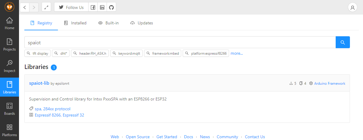
- available in the PlatformIO Library Manager and as a ZIP file for the Arduino IDE.
spaiot-lib allows the integration of your Intxx PxxxSPA into your home automation (Internet of things). For example, associated with SinricPro, spaiot-lib will order its spa in the voice using a Google Assistant, Amazon Alexa...

spaiot-lib is based on Geoffroy Hubert's work on the DIYSCIP project. It is published with the same license: Creative Commons Attribution - No commercial use - sharing under the same conditions.
:warning: disclaimer: This project is not affiliated with Intxx.
It is distributed in the hope it will be useful but WITHOUT ANY WARRANTY. Any damaged on your spa or lost of original product warranty is in your own responsibility, including any consequences of using this project.
spaiot-lib provides the following features:
- decoding frames on the connection between the control panel and the motor block to monitor the status of the spa,
- remote control of push buttons
It is documented using doxygen and delivered with examples. Unit tests provide continuous integration and delivery (CI/CD)
Installation
VS Code & PlatformIO
- Install VS Code
- Install PlatformIO
- Install spaiot-lib by using Library Manager
- Use included platformio.ini file from examples to ensure that all dependent libraries will installed automaticly.
ArduinoIDE
- Install Arduino IDE
- Install Arduino core for ESP8266 or ESP32
- Install spaiot-lib by using Library Manager, spaio-lib is available in the Arduino Library Manager
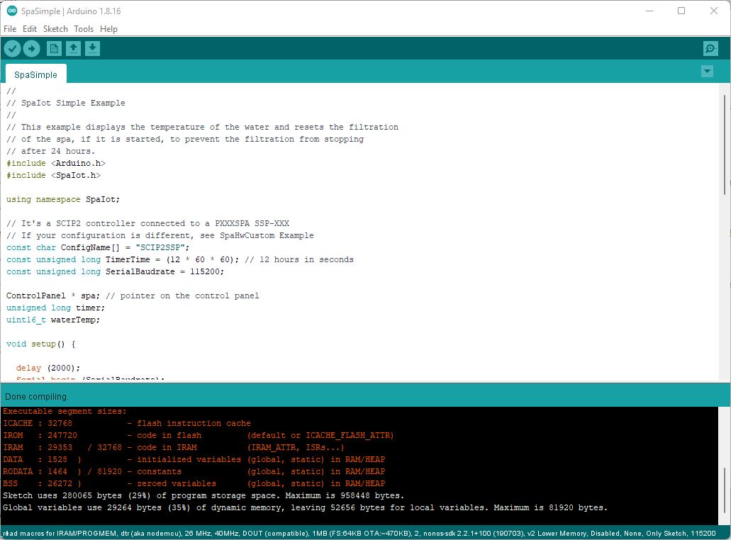
When you add the library successfully, there will be a demo in the Example. In this case, click on File > Example > spaiot-lib > SpaSimple to open an example.
Choose the highest CPU frequency (160MHz for ESP8266, 240MHz for ESP32) from the Tools > CPU Frequency menu, click on the Verify button, if there's no error, congratulation, the library is installed perfectly.
Full user documentation
The first-level API consists of the SpaIot::ControlPanel class. For simply use, so just read the documentation of this class.
For more advanced development, full documentation is available.
Please see here for full user documentation
Examples
See examples on GitHub
Usage
- Declare a global variable on the
spacontrol panel
- In
setup()
- In
loop(), use API of the ControlPanel class to do or read what you want
Configure the library according to the electronic part and the spa model
spaiot-lib comes with hardware configurations and SSP-XXX and SJB-XXX SPA models :
- SCIP2SSP > DIYSCIP v2 and SSP-XXX spa
- SCIP2SJB > DIYSCIP v2 and SJB-XXX spa
- SPAIOT8266SSP > SpaIot ESP8266 Version and SSP-XXX spa
- SPAIOT8266SJB > SpaIot ESP8266 Version and SJB-XXX spa
- SPAIOT32SSP > SpaIot ESP32 Version and SSP-XXX spa
- SPAIOT32SJB > SpaIot ESP32 Version and SJB-XXX spa
- SPAIOTS3SSP > SpaIot ESP32-S3 Version and SSP-XXX spa
- SPAIOTS3SJB > SpaIot ESP32-S3 Version and SJB-XXX spa
- SPAIOT328574SSP > SpaIot ESP32 Version with PCF8574 Mux and SSP-XXX spa
- SPAIOT328574SJB > SpaIot ESP32 Version with PCF8574 Mux and SJB-XXX spa
- SPAIOTS38574SSP > SpaIot ESP32-S3 Version with PCF8574 Mux and SSP-XXX spa
- SPAIOTS38574SJB > SpaIot ESP32-S3 Version with PCF8574 Mux and SJB-XXX spa
But it possible to adapt the hardware configuration with the HardwareSettings class which is an aggregation of classes:
- BusSettings that defines the configuration of the synchronous serial link,
- LedSettings that defines the configuration of the LEDs of the spa,
- ButtonSettings that defines the configuration of the buttons.
You can see how to create your own configuration with the SpaHwCustom example
Before declare a global pointer on the spa control panel:
- Describe the pins used by the bus using a BusSettings constant
- Describe the bits of the frame used by LEDs using a list of LedSettings type constants
- Describe buttons controllers and their pins with the corresponding class (here Multiplexer)
- Describe the (bits used in the frame and controller) using a List of ButtonSettings constants
- Finally Create the hardware configuration
How does SpaIot work ?
Decoding frames
Decoding requires only 3 GPIO pins of the ESP chip. These pins are connected to the SDATA, SCLK and nWR signals of the bus between the control panel and the motor block. These 3 signals constitutes a synchronous serial bus (similar to the SPI bus) that transmits frames consisting of 16-bit words. The words are composed of 2 bytes A and B. B is the most significant byte and it is transmitted first. Bytes are transmitted with the most significant bit first (left).
We can see in the image below the frame that corresponds to the command of the LEDs:
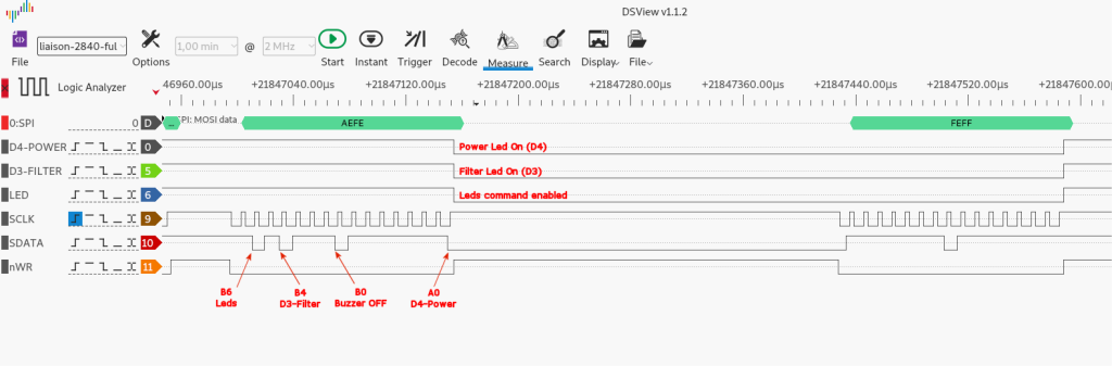
Decoding is implemented by the FrameDecoder class. This class makes it possible to recover mainly the following information:
- LED status using FrameDecoder::isPowerOn(), FrameDecoder::isFilterOn() ...
- measured water and desired temperature using the FrameDecoder::waterTemp() et FrameDecoder::desiredTemp(),
- error code displayed using the FrameDecoder::error() function
The GPIO pins connected to the SCLK and nWR signals are used in interruption. That's why the Framedecoder class is a singleton. It is designed to be a base class and can not be instantiated directly. It will be used thanks to its ControlPanel derived class.
Control of push buttons
The general idea is to "connect" an electronic switch to bypass the button on the control panel. Of course, this is not what is done because it would be necessary in this case to intervene on the control panel.
To find out how to do it, simply study the diagram below:
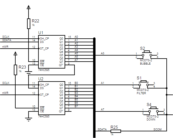
It is possible to see 2 integrated circuits, U1 and U2 which will store the 16 bits of the frame and apply their logic level to the correditional pins of U1 / U2. U1 memorizes least significant byte A, U2 the most significant byte B.
To play a push button:
- The button must be selected by transmitting a 16-bit word that applies a low level to a pin of this push button,
- Then put nWR in the top state,
- Activates a pull-up resistance on SDATA,
- Toggle the signal SDATA input,
- Then after a delay of a few microseconds, to read the state of SDATA, which is connected to the other pin of the button.
If SDATA is in the low level, the button selected in step 1 is pressed. For example, if we want to test if the S1-Filter button is pressed, you have to send a word with bit A1 to 0.
To be able to emulate pressing a button, it is necessary to reproduce this scheme on a board and replace the buttons with electronic switches.
MOSFET transistors can be used, multiplexer circuits... In version 2 of the board, the DIYSCIP project uses 2 multiplexer circuits 1 to 8 (4051) that allow to take into account any button connected to A0..A7 or B0..B7
spaiot-lib implements the button control with the Button class. Button uses the Abstract ButtonController class to make the connection between the button of the button and SDATA (SCOM actually). Thus, the developer will be able to create a derived class of ButtonController to implement his solution.